
Sewer Exploring Robot!
In this post, I describe our senior design project: the sewer exploring robot! We presented this in the senior design showcase in May of 2014, and were awarded 1st place in the competition! This is how it came together…
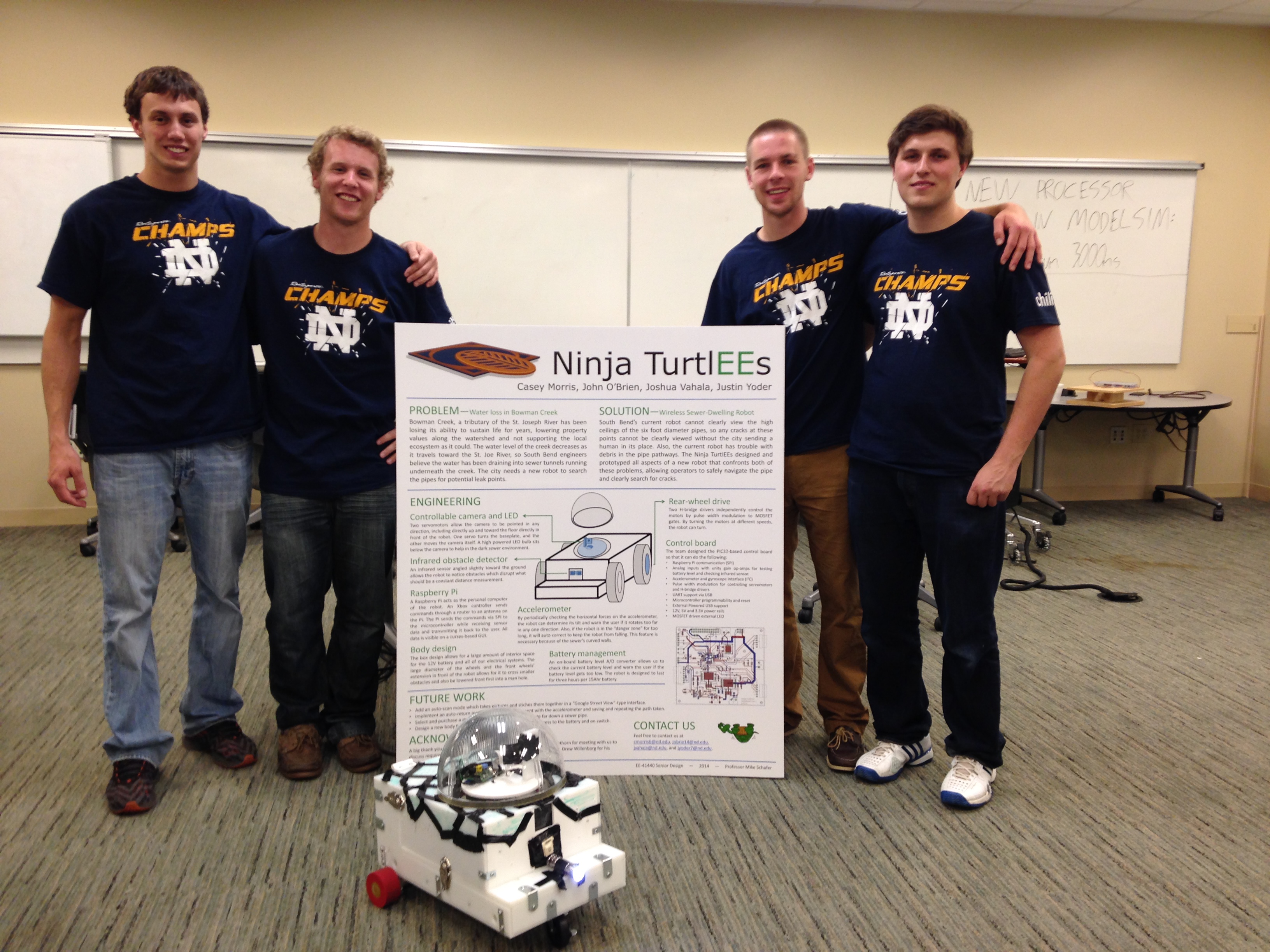
The Ninja TurtlEEs
The 2014 Notre Dame Electrical Engineering class had 39 graduates, and we were able to assemble the best possible team: John O’Brien, Josh Vahala, Justin Yoder. Due to our project based on the idea of a sewer exploring robot, our team was aptly name: The Ninja TurtlEEs
Requirements
Perhaps the most exciting and most useful class during my undergraduate studies was Senior Design. The requirements were loose:
- Work in a team of 4 to design an embedded system
- Must use the PIC32 uC and a serial interface
- Must incorporate a custom PCB
- $500 budget for all parts
It was up to our team to come up with some sort of project idea and to devise the plan to implement the project.
Problem Description
In the class portion of Senior Design, a representative for the city of South Bend gave a talk describing some of the challenges facing the city and asked for ideas in which our project could be of use. We were 1 of only 2 teams that geared our project to the city’s needs, and the idea we came up with was our sewer exploring robot.
The city explained a problem they had with the old infrastructure of their sewer pipes, and these were susceptible to leaking. One particular area where this was an issue was Bowman Creek. Here, the sewer tunnels crossed the tributary of the St. Joseph’s River, and any leaks had the potential to contaminate the water supply, damage the sewer, or both. To detect a leak, a special dye was placed in the water of the river, and the sewer tunnels were searched for traces of this dye. However, it was a great risk and expense to the city to have human workers lowered into the tunnels to search for the leak. Some sorts of specially designed robots were available for purchase that could roam the tunnels looking for leaks, but they too were too expensive for the cash strapped city.
This issue was of interest to our team due to both the potential positive impact it could have on the city, and also the variety of different technologies and features the ideal solution would require. The potential project certainly went above and beyond the base requirements for the project, but we were up to the challenge.
Robot Design
We worked with the representative from the city of South Bend to come up with a set of requirements and features our project would entail. Some of the high level design requirements were as follows:
- Remote control capability of the robot wirelessly
- Capture video and stream in real time.
- Control camera angle in 3 dimensions
- Battery powered motor drives
- Ability to sense obstacles in tunnel
- Level Sensing
- Waterproof enclosure
Wireless Communication
Perhaps the biggest unknown when we started the project was how to handle the wireless communication. We needed a wireless link to be able to send remote control commands to drive the robot. There was discussion as to using WiFi, Zigbee, or Bluetooth, but because we were going to also be streaming video, we decided to go with WiFi.
The uC that we were required to use was a PIC32, which did not have much support for WiFi. While we could have designed a board with a dedicated WiFi module and antenna, this was well out of scope for the project (and even further outside our capabilities). Instead, we decided to include a Raspberry Pi 3 module. This was 2014, before the wifi capability was built in the RPi, though it did have all networking capabilities. Our solution was to add a USB WiFi dongle to the RPi. This allowed the Pi to connect to the ad-hoc WiFi network we created with a router, and then the RPi was connected to our uC via an SPI bus. The RPi was used solely for WiFi communication and video streaming, all other processing, such as motor control, prox sensing, etc. was processed in the PIC, per class requirements.
Thus, the data data flowed as such: from the remote host client (to be discussed) over WiFi to the RPi via a TCP port, then to the PIC via SPI. Data was then sent back to the host from the PIC in the reverse manner.
Video Streaming
The most critical part of the project was the ability to live stream video. This would allow a human to view the inside of the tunnel in real time from ground level, and aided the steering ability. To accomplish this, we also relied on the RPi Camera module. This was a low cost (and relatively low quality) solution that integrated easily with the RPi. The RPi then launched an RTSP video network stream that we then opened in a VLC player on our host client to view the video live. The video streaming capability was mostly baked into the RPi, which greatly eased the amount of work on our side.
Remote Control
Being able to control the robot remotely was of great interest to our team. There were actually 2 different things we wanted to control remotely: 1) The steering/direction/speed of the robot, and 2) The Angle of the Camera. As a result, we wanted to use some sort of remote that had two different joysticks so that we could control both simultaneous.
The remote that we ended up choosing to use for the project was a USB XBOX controller. The controller was connected to a Linux machine, and we used open source drivers to read the status of the controller and stream the joystick positions. We wrote a C program running on the Linux host to process the data from the controller, to open a TCP port to the RPi on the robot, send the controller commands to the PIC, and to display sensor data that is returned from the robot. We created a custom packet protocol to exchange the desired commands for the servos and the motors, and read the state of the PIC. Likewise, created an API for the RPi to communicate with the PIC via SPI.
Camera Control
The camera was mounted using 2 different servo motors. The first was a traditional hobby servo that had about 270 degrees of rotation. The position of the servo is controlled by the width of the PWM pulse applied to its input. This servo controlled the tilt angle of the camera (in the Z direction), so changing the PWM duty cycle moved the camera angle up and down.
The other servo used to control the camera was a 360 degree continuous servo. This servo is able to spin continuosly. This is controlled differently in that the speed and direction of the servo spinning is controlled by the width of the PWM pulse, and a duty cycle of 50% held the servo steady. This servo was used to control the pan angle of the camera, so we were able to have a 360 degree view of the sewer from the robot at all times.
Motor Control
The entire system was powered by a 12 V battery. We used two standard DC motors to directly drive the back two wheels of the robot. The motors where controlled via a special H-Bridge circuit that was provided by our instructor. We input a PWM pulse to the H-Bridge to apply power to the motors. Turning was accomplished by applying different speeds to each motor (though we didn’t have a differential, so turning was rough).
Other Sensors
We were interested in including a couple other sensors on board the robot, namely 1) a proximity sensor and a 2) gyrometer. The prox sensor would be used to alert the robot (and the controller) when the robot was nearing an obstacle. The gyrometer was used to measure the stability of the robot. This information was relayed to the Linux host so the controller had an idea if the robot was becoming unstable.
Mechanical Difficulties
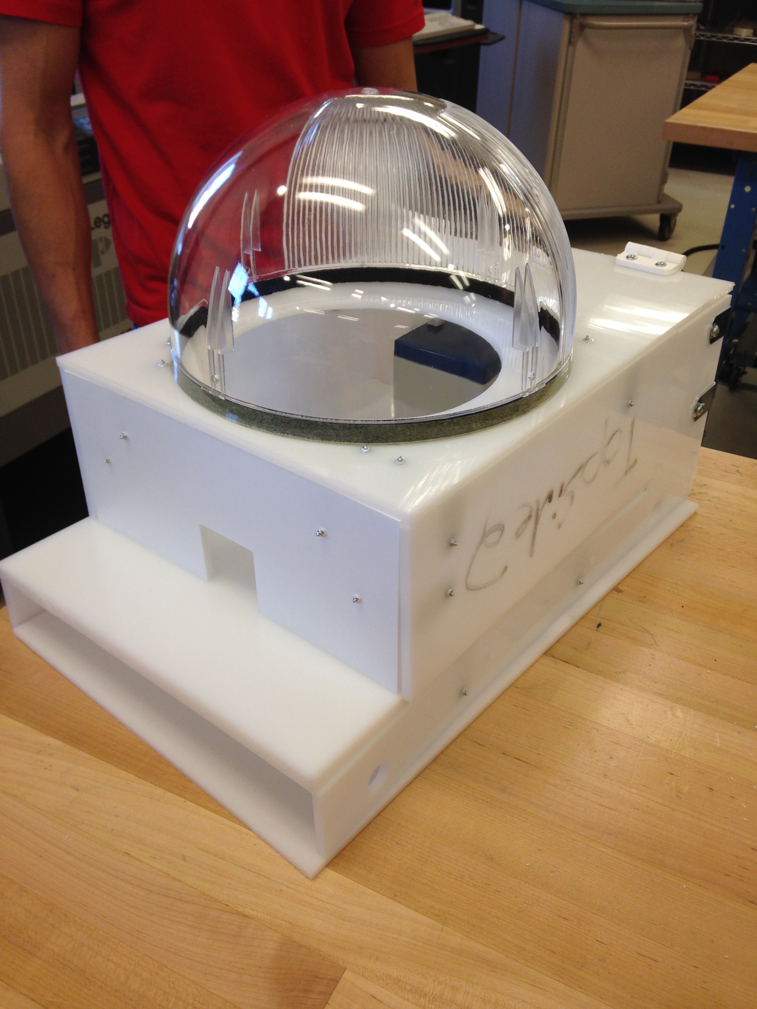
While the electrical and software challenges were in our area of expertise, the most difficult part of the project was the mechanical design. As mentioned, one of the ideal requirements was that the body be waterproof. Though the prototype we were making would not be exactly waterproof at the edges, we took care to ensure everything was securely enclosed, including the camera casing.
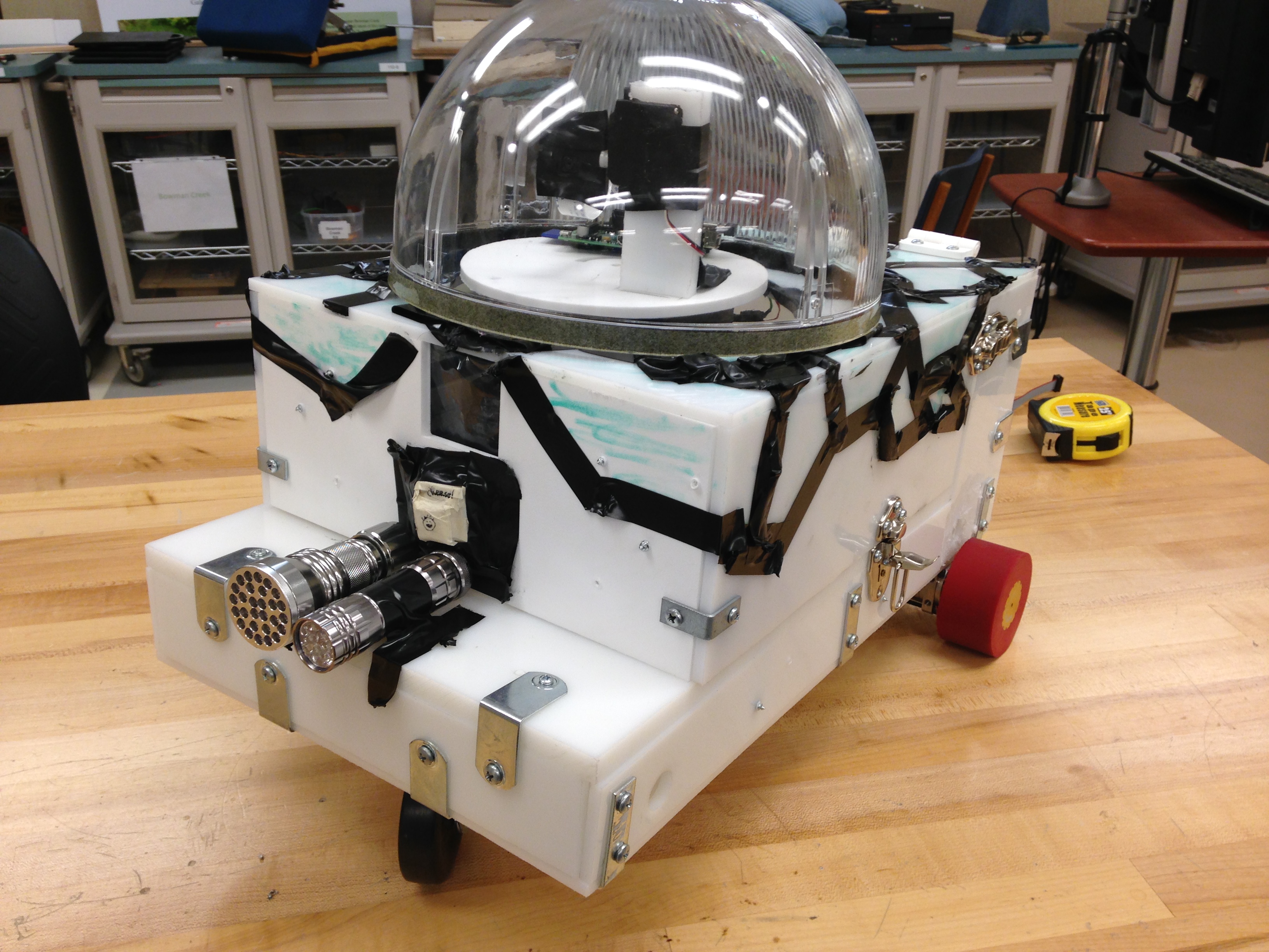
In addition to waterproofing, designing a robot body and attaching motors, wheels, etc. was a gigantic challenge. It needed to be secure, but also easy to access the insides for testing and development. Below shows the end result of the body; a boxy, ugly mess of plastic with a hinge. We were happy that aesthetics were not part of the criteria for the prototype!
Mounting the axles and wheels to the body was another huge task, and we soon learned that wheel system we implemented was not conducive to turning (no area for the wheel to turn without hitting the body of the robot). This caused some major headaches. Remarkably (and with the help of some mechanical friends and their CNC skills), we were able to put together a serviceable robot!
Live Demo
Once we were able to assemble the robot and had all of the functionality (mostly) working, we arranged for a live demonstration using the sewer tunnels on campus. With the help of a member of the maintenance department, we lowered our robot into the tunnel, turned it on, and voila! Everything worked as expected! We controlled the robot for a couple hundred feet down the tunnel, streamed video back to the host and moved the camera all around to inspect the walls. We saved this video, and were excited to relax until the senior design demo the next afternoon. That was until, however, disaster struck with about 20 hours until the demo….
Disaster
The major design flaw in our design was our motor control. It was not until a year later in my motor design classes in graduate school that I would really understand what was our kryptonite. The main issue though was that we were using those DC motors, which at high frequencies, have a very high impedance. When the motors were off and in a stall state and we applied power to them through the H-Bridge circuit, in the instant the power was applied, the motor impedance can cause a giant current spike until eventually the rotor begins to spin. In traditional applications of DC motors, there are “starter capacitors” that are used to slowly (not instantaneously) apply voltage to the stator of the motor until it begins to turn. However, if not designed properly, this giant current spike can cause issues, which we would soon learn.
After our successful demo in the tunnels, we decided we just wanted to fine tune a few things before the big expo the following day. One of the main things we wanted to improve was the turning (which was rough as described before). In the course of testing that afternoon, in the middle of a turn, one of the wheels got stuck, and we happened to stall the motor. This led to a giant current spike, which in turn caused a huge ground noise spike (we had no isolation), and this fried all of our electronics. The H-Bridges legitimately caught fire (just a small flame), and pretty much all of our other electronics on our board were toast. The PIC, fried. The Prox Sensor, fried. The board was unusable. And we had 20 hours until the demo day…
Probably due to our youth, I don’t recall any of us freaking out too much. We were more in a state of shock and bewilderment. It was almost funny that our yearlong project had literally blown up hours before the due date. Instead of panicking, we collectively entered survival mode: i.e. we need to pass this class to graduate mode. Thankfully, we had video of the robot working in the tunnels so we were pretty sure we wouldn’t outright fail the class, but we desperately wanted something to demonstrate the next day.
We were fortunate in a couple senses: the RPi was saved (we didn’t have an extra one), we had ordered extra PCBs and parts for the board - which would need assembled ASAP. Additionally, the mechanical engineering classes were using the same prox sensors we were using, so we were able borrow one of their extra ones. However, the main issue left to figure out was how to drive the robot. As mentioned, the H-Bridge circuit had gone up in flames (literally) and even if we had enough parts to recreate it, we couldn’t be sure that it would survive until the next day.
At this point, we had to be creative. Again, luckily we had friends in mechanical engineering. For their projects, they were also making robots (much better looking than ours, but their electronics were sub par). Thus, there were extra motor drives, motors, and wheels lying around. We salvaged as many parts as we could find and completely redid the powertrain system for the robot. In addition to the mechanical differences, it involved different motor control PWM techniques that needed to be implemented, calibrated, and tested. Now that we had at least figured out a potential solution to save our project, we just had 20 hours to do all of the work.
As a result, it was on this day, the second to last day of my undergraduate career, I had to pull my first all nighter. As an aside, I am generally against the idea of an all-nighter and did not see much point in them throughout college. While many of my friends resorted to them, I always valued sleep more than the extra few hours of studying and found the sleep to be a more efficient use of my time when it came to school work. However, this was a special situation: the work to be done was known, just took time, and we were running on adrenaline. It was a whirlwind of an evening/night/morning, but somehow the sun rose the next day and we had a robot.
Presentation Day
To say we finished the modifications and last minute changes to the robot in the knick of time would be an understatement. We were in the lab tinkering/calibrating the robot (we needed to add reversing capability!) until 5 minutes AFTER the demo was scheduled to start. Luckily, things were running a few minutes behind which allowed us to finish and bring the robot from the lab to the demo floor as it opened. At this point, the adrenaline has begun to fade - we did it! - and we are a bit tired, but we proceed to show off the robot throughout the afternoon to the visitors of our booth. Things seem to go off without a hitch, the robot works, we show the video from the day before. Everyone loves it. We are relieved. It was later announced at graduation that we won 1st place in the design competition!!
That 20 hour period before the demonstration day definitely ranks up there as one of the most stressful, exhilarating, craziest times of my life. It was an incredible challenge, but one we embraced head on. We absolutely had an amazing team, to be able to accomplish what we overcame was so rewarding. If I ever need a team of 4 to take on a seemingly impossible challenge, I know who my first 3 calls will be.
Takeaways
The senior design class was far and away the most useful class with regards to my career that I have taken. We practiced skills such as project management, product requirement gathering, specification writing, etc. We also learned the most applicable technical knowledge with topics such as serial communication, I2C, SPI, PCB design, uC development, interrupts/ISRs, UART, the list goes on (and I’m not sure why we didn’t learn these things earlier!). This class also gave us the confidence to go out into industry knowing we could accomplish anything, even if we had no idea where to start. And for this, I am eternally grateful. Thanks, Prof. Schafer.