
Custom RFID Lock and Lighting System
This post details the custom lighting and locking solution that my roommate and I implemented at our apartment in graduate school to improve our living experience. Little did I know it would foreshadow my eventual job at Orro!
Project Inception
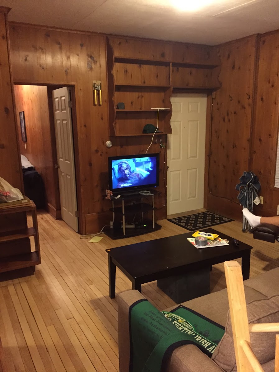
In graduate school, my roommate, Josh Vahala, and I lived in a pretty great apartment a few blocks from campus, walking distance to pretty much everything we needed (especially Trader Joe’s). However, it was an older apartment and did not have some of the basic features of current houses, namely overhead lights in the living room. Lighting was done via lamps connected to switch-controlled outlets, and the locations of the switches were wildly inconvenient. Most frustrating was the living room switch being at the complete opposite side of the room from the front door, meaning arriving to an empty house after dark meant fumbling across the living room; a treacherous task. The living room is pictured below, showing the front door but no switch in the picture!
By the time winter in Madison rolled around, the sun was setting earlier and earlier, and we grew more frustrated with the light setup. In addition, we were tired of fumbling around with our keys in the freezing cold trying to open the door. Out of these issues, our DIY home locking and lighting system was born.
System Design
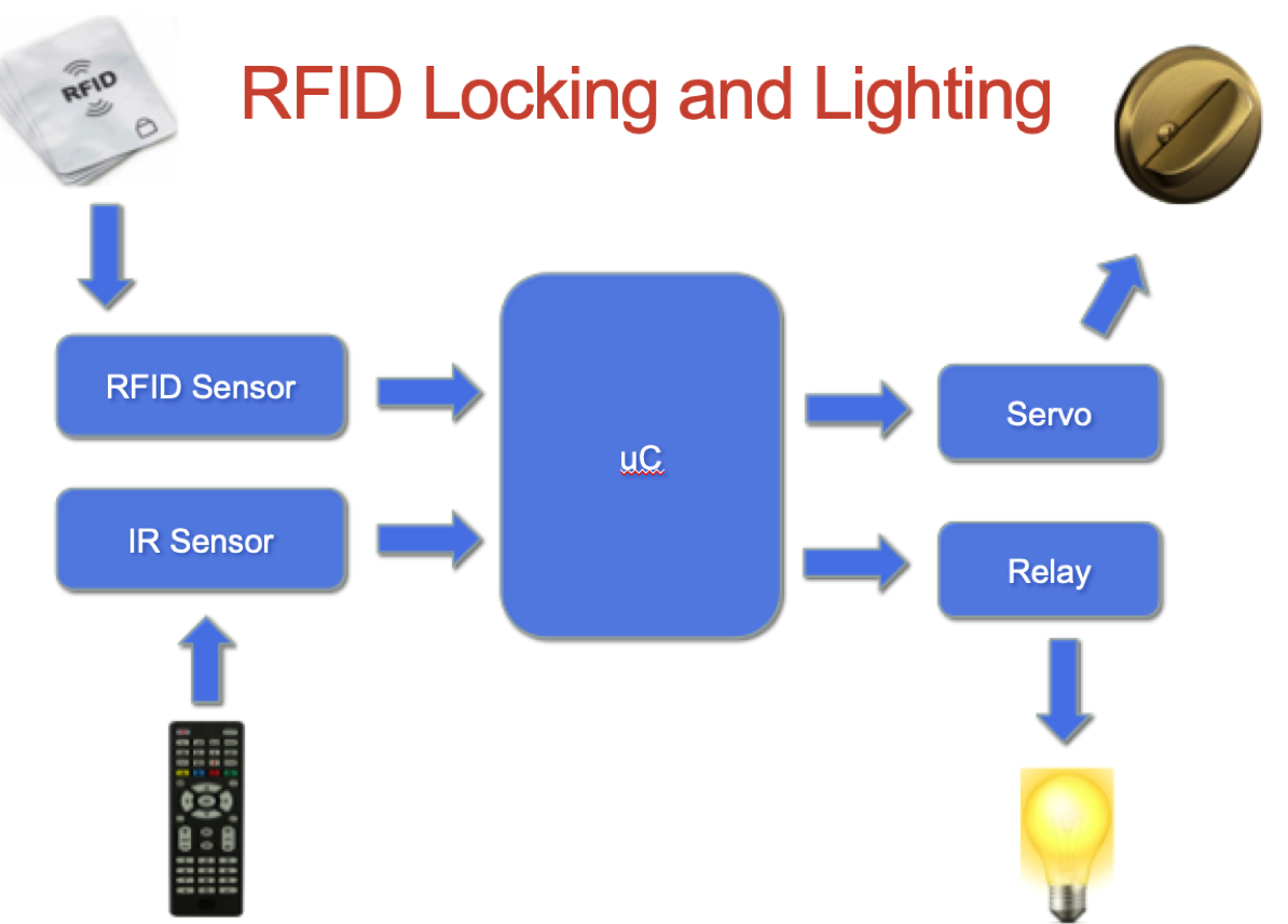
We had two objectives in desiging our system: 1) we wanted to add a light switch mechanism near the entry way; 2) we wanted some way to unlock the door autonomously. To accomplish the light control, we decided to use a relay, and for the lock we used an RFID reader and a hobby servo. Below is the system overview we decided to implement.
Hardware Requirements
- Arduino Uno with Power Supply
- Powerswitch Tail Relay
- IR Sensor
- Servo Motor
- RFID Sensor
- Various LEDs, wires, switches
Lighting Control
The first task we decided to tackle was the lighting control. We wanted to create our own sort of light switch that we could place near the door, but we also wanted the light to be remote controlled. Using the arduino uC as the system controller, we sensed the state of a simple toggle switch. When this toggled, we toggled the light via the use of the PowerTail relay. Outputting a digital HIGH or LOW controlled the relay, therefore toggling the light.
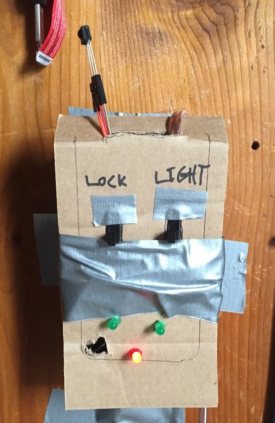
For the remote control functionality, we used a basic IR sensor and an old TV remote. When the power button of the remote was detected, we similarily toggled the state of the light via the relay. The light switch, Arduino, and IR sensor were contained in 1 enclosure, and we used speaker wire to run the relay control signal around the room to the lamp and relay. The picture and video below shows an early prototype of the enclosure and the light controlled via the remote.
Lock Control
Because we were tired of fumbling with our keys in the Madison winter to unlock the door, we wished for a fast and convenient way to unlock it. That would mean some sort of mechanism to actuate the lock and an easy way to trigger the actuation. The logical choice was an RFID card reader! We already used our student ID RFID cards to unlock buildings around campus, our apartment was a natural next step.
The hardest part of this project was certainly the locking mechanism. We knew we wanted to use the servo to move the deadbolt, but we had all sorts of trouble finding a reliable way to attach the servo to the lock. We toiled away at this task for longer than either of us would probably like to admit. Evetually, with some help from several of our mechanical friends, we designed the system explained below:
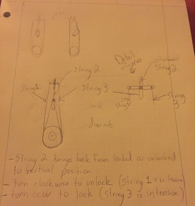
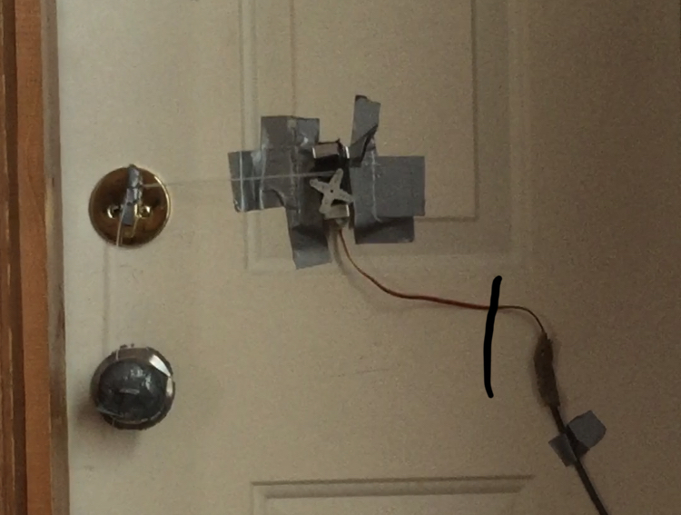
We had issues maintaining string tension and eventually had to abandon the ability to also lock the door. It was a tradeoff we were willing to make for the ability to unlock. The final implementation of the unlocking system was not by any means appealing to look at (see below), but it worked reliably!
At this point, we had a finally had all of the functionality working. We then added the logic to automatically turn the light on when the RFID unlocked the door, and we added the ability to unlock the door with the remote (in case any visitors knocked, we could unlock from the couch!). The only thing left was to create a presentable enclosure.
Enclosure Design
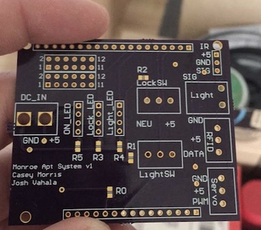
Because we wanted to fit all of this functionality into a small system controller enclosure, and not have a bunch of bread boards and wires hanging around the apartment, we needed a custom board to route all the signals to the sensors, etc. We decided to create a custom “shield” for the Arduino so we could easily connect our custom cables that connected to the relay, RFID sensor, and servo. We used Altium Board Designer and produced the following board. With this board, we were able to fit the processor and cables neatly into one system.
Smart Home Living
Eventually, everything finally came together and we lived in comfort with the conveniences now afforded to us with our improved lighting and locking system! Below are two vidoes of how the system worked from the inside and outside!
Frozen Out
The system was working great and we were doing our best managing the sub 0 temperatures in Madison that winter. Unfortunately, one fateful night, it was so cold that it fell below the rated operating temperature of the RFID sensor that was on the outside of the apartment. This broke the RFID sensor and served as a good lesson in the impact of operating conditions in system design!